That my friend, is the right question*. So I've been pondering about purpose. Its been an interesting exercise experimenting with some different types of object detection and avoidance with the most successful version using ultrasonic sensors.
So I have a robot that can move around the house and not run into things. It's cool but there is no purpose to what it does, aside from avoidance. In order to give the robot a purpose or a reason to move, I'm going to have it move toward a sound source (and avoid obstacles on the way).
I'm also going to mount the ultrasonic sensor on a pan&tilt servo so it can figure out the best way to get out of a corner. Another addition will be a current sense to detect high current draws if it does run into something.
I have the pan&tilt assembly, just waiting for the current sense. I'll also purchase two Arduino sound modules that output both raw audio and sound pressure readings. This will allow the robot to detect and track towards/follow a sound source. It will use the ultrasonic sensor for object avoidance in combination with current sense.
I'll keep this blog uptodate with progress of the experiments.
*To paraphrase a quote from the movie AI.
Sunday, May 6, 2012
Sunday, April 8, 2012
Object collision avoidance test #2
I've replaced the IR sensor with an ultrasonic sensor. The new sensor actually returns the distance from the object, so the robot can be programmed to avoid object by proximity. In this version it is only forward looking, so it still can't see what is beside or behind it but it manages still to get itself out of tricky corners. Eventually it does get stuck in a corner, however using a pan & tilt assembly for the sensors will allow it to 'look around' and find a solution out of a tight spot.
Once again, the code is very simple:
Once again, the code is very simple:
#define MOTOR_OFF B00000000;
#define MOTOR_FWD B10010000;
#define MOTOR_REV B01100000;
#define MOTOR_LFT B10100000;
#define MOTOR_RHT B01010000;
#include "Ultrasonic.h"

Ultrasonic ultrasonic(12,13);
int distance = 0;
const int maxDistance = 100;
const int range = 25;

void setup() {
PORTD = MOTOR_OFF;
delay(500);
PORTD = MOTOR_FWD;
Serial.begin(9600);
}


void loop() {

distance = ultrasonic.Ranging(CM);

if(distance < range) {
 PORTD = MOTOR_OFF;
 do {
    distance = ultrasonic.Ranging(CM);
    if(distance > maxDistance) {
    delay(5);
    distance = ultrasonic.Ranging(CM);
    continue;
   }

  PORTD = MOTOR_REV;
  }  while(distance < range);
  PORTD = MOTOR_OFF;
  PORTD = MOTOR_LFT;
  delay(1000);
  PORTD = MOTOR_OFF;
  PORTD = MOTOR_FWD;
  }
}
Saturday, March 31, 2012
First object avoidance test.
This short video demonstrates the first attempt at object avoidance using IR. It seems to partly work in that it will detect objects in motion, but it won't detect an object that its moving towards. The IR emitter was removed from an old remote and the IR receiver module was pulled from an old appliance. The receiver works on a 38Khz - 40Khz carrier which is modulated via a command code specific to the device.
Timer2 on the Arduino was set to run at 40Khz continuous. I tried modulating the carrier to simulate the output from a commercial remote and tried the Arduino IR library but couldn't seem to get it to detect stationary objects. It would seem that IR receivers designed for remote control application are suitable for use in detecting objects - party because it does not indicate distance, it presents only TTL output.
There are IR sets out there that do provide output proportional to distance from object and these would obviously work well in this application. The other object of this test was to try out the L298 dual bi-directional motor controller module (H-bridge). It works very well and is easy to use.

So, my plan to build an army of evil robots to help take over the world will have to wait a little longer......:)
The code for this test is very simple:
Timer2 on the Arduino was set to run at 40Khz continuous. I tried modulating the carrier to simulate the output from a commercial remote and tried the Arduino IR library but couldn't seem to get it to detect stationary objects. It would seem that IR receivers designed for remote control application are suitable for use in detecting objects - party because it does not indicate distance, it presents only TTL output.
There are IR sets out there that do provide output proportional to distance from object and these would obviously work well in this application. The other object of this test was to try out the L298 dual bi-directional motor controller module (H-bridge). It works very well and is easy to use.

img src - http://www.ebay.com.au/itm/280714490010?ssPageName=STRK:MEWNX:IT&_trksid=p3984.m1439.l2649
So, my plan to build an army of evil robots to help take over the world will have to wait a little longer......:)
The code for this test is very simple:
#define MOTOR_OFF B00000000;
#define MOTOR_FWD B10010000;
#define MOTOR_REV B01100000;
#define MOTOR_LFT B10100000;
#define MOTOR_RHT B01010000;

int sensorPin = 2;
int sensorValue = LOW;
int irON = false;


void startIR() {
TCCR2A = _BV(COM2A0) | _BV(WGM21) | _BV(WGM20);
TCCR2B = _BV(WGM22) | _BV(CS20);
OCR2A = B11000111;
}

void stopIR() {
TCCR2A  = 0;
TCCR2B = 0;
}

void setup() {
pinMode(11, OUTPUT);
pinMode(sensorPin,INPUT);
PORTD = MOTOR_OFF;
delay(500);
PORTD = MOTOR_FWD;
startIR();
Serial.begin(9600);

}


void loop() {
sensorValue = digitalRead(sensorPin);

if(sensorValue == LOW) {
Serial.println(sensorValue);
PORTD = MOTOR_OFF;
delay(500);
PORTD = MOTOR_LFT;
delay(1000);
PORTD = MOTOR_OFF;
delay(125);
PORTD = MOTOR_FWD;
delay(125);

}

}
Monday, March 26, 2012
The Cylon eye / Knight rider effect.
Using the same circuit arrangement as previously posted, we can turn our simple light meter into a Cylon eye! This shows the flexibility of the Arduino and how powerful software can be:
The effect could probably enhanced by adding capacitors between the base and ground on each transistor, causing the adjacent LEDs to fade in/out.
int counter = 0;
int direction = true;


void setup() {
 PORTD = B00000000;
 pinMode(0,OUTPUT);
 pinMode(1,OUTPUT);
}

void loop() {
 if(direction) {
   counter++;
   if(counter == 7) {
     direction = false;
   }
 }
 else {
   counter--;
   if(counter == 0) {
     direction = true;
   }
 }
 PORTD = 1 << counter;
 PORTD = PORTD | 1 << counter + 1;
 delay(80);
}
The effect could probably enhanced by adding capacitors between the base and ground on each transistor, causing the adjacent LEDs to fade in/out.
Sunday, March 25, 2012
Simple light meter
This Arduino project is a simple light meter using a photo-transistor. An LDR would be more appropriate but the photo-transistor is what I had on hand. On the other hand the photo-transistor is sensitive to infrared, so its handy for testing that remote control.
The project consists of 10 red LEDs driven by 10 BC547 transistors. Any general purpose transistor will do. The base of each transistor is connected to the Arduino board digital pints D0 through to D7 via a 2.2K resistor. The LEDs are connected to a 12 volt source with current limiting resistors of 560 ohms.
The input is provided by a photo-transistor connect to the Arduiono's analogue input on analogue pin 0. The range of the input for the photo-transistor is 0 (full light) to 1023 (full dark), 1024 in total. This output is divided by 128, that is the full range (1024) divided by the number of LEDs (8). As the result is cast as a floating point, we round it up to the nearest integer. So 7.5 become 8. Finally we subtract this result from the total number of LEDs.
A simple for loop is used to enumerate the result and light/extinguish the appropriate number of LEDS. The source below:
 Click to enlarge.
The project consists of 10 red LEDs driven by 10 BC547 transistors. Any general purpose transistor will do. The base of each transistor is connected to the Arduino board digital pints D0 through to D7 via a 2.2K resistor. The LEDs are connected to a 12 volt source with current limiting resistors of 560 ohms.
The input is provided by a photo-transistor connect to the Arduiono's analogue input on analogue pin 0. The range of the input for the photo-transistor is 0 (full light) to 1023 (full dark), 1024 in total. This output is divided by 128, that is the full range (1024) divided by the number of LEDs (8). As the result is cast as a floating point, we round it up to the nearest integer. So 7.5 become 8. Finally we subtract this result from the total number of LEDs.
A simple for loop is used to enumerate the result and light/extinguish the appropriate number of LEDS. The source below:
int sensorPin = A0;The results can be seen in this quick video showing how the LEDs react when a torch is brought near the photo-transistor.
float sensorValue = 0;
int leds = 8;
int result = 0;
int divisor = 128;
void setup()
{
PORTD = B00000000;
pinMode(0,OUTPUT);
pinMode(1,OUTPUT);
}
void loop() {
sensorValue = analogRead(sensorPin);
result = leds - round(sensorValue / divisor);
for(int i = 0;i < leds;i++) {
if(i < result) {
digitalWrite(i,HIGH);
} else {
digitalWrite(i,LOW);
}
}
}
 Click to enlarge.
Saturday, March 24, 2012
My Arduino adventures.
This is a small blog to help me keep track of my little Arduino projects. Most of them will small and simple as I'm learning as I go. For those of you who don't know, the Arduino is a SBC (single board computer) when can do practically anything you can imagine.
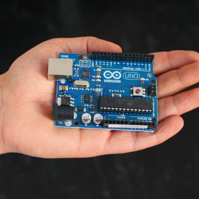 Image src: http://www.arduino.cc
There is an easy to use IDE (integrated development environment) that will compile, check and download your code to the Arduino board via its USB cable, its that simple!
Programming for the Arduino is based on C++ and with the help of its friendly API, makes programming a breeze:
The other great thing about the Arduino board is that it provides a large number of interfaces including PWM (pulse width modulation) and analogue inputs which makes it easy to add hardware to control or receive information from.
The are also inexpensive. I purchased an Arduino clone by Freetronics from Jaycar for $39.00. So if you like playing with software and hardware, go get yourself an Arduino board and have some fun!
Image src: http://www.arduino.ccThere is an easy to use IDE (integrated development environment) that will compile, check and download your code to the Arduino board via its USB cable, its that simple!
Programming for the Arduino is based on C++ and with the help of its friendly API, makes programming a breeze:
/*This example will flash the onboard LED, it doesn't require any additional hardware.
Blink
Turns on an LED on for one second, then off for one second, repeatedly.
This example code is in the public domain.
*/
void setup() {
// initialize the digital pin as an output.
// Pin 13 has an LED connected on most Arduino boards:
pinMode(13, OUTPUT);
}
void loop() {
digitalWrite(13, HIGH); // set the LED on
delay(1000); // wait for a second
digitalWrite(13, LOW); // set the LED off
delay(1000); // wait for a second
}
The other great thing about the Arduino board is that it provides a large number of interfaces including PWM (pulse width modulation) and analogue inputs which makes it easy to add hardware to control or receive information from.
The are also inexpensive. I purchased an Arduino clone by Freetronics from Jaycar for $39.00. So if you like playing with software and hardware, go get yourself an Arduino board and have some fun!
Subscribe to:
Posts (Atom)